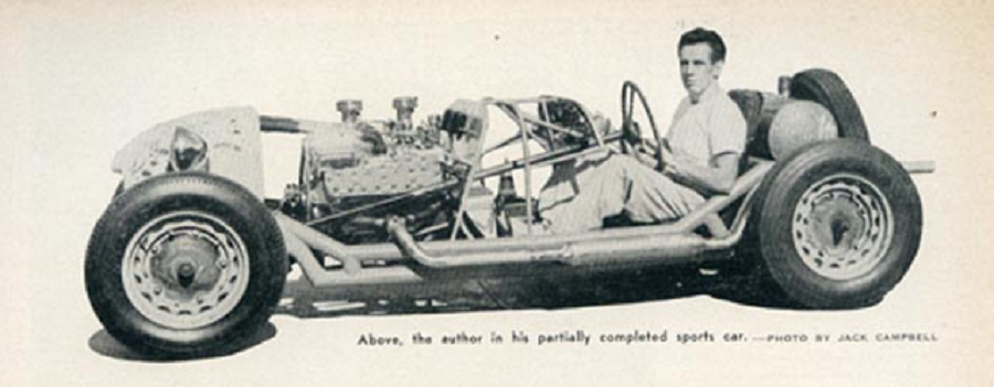
———–
Note: This is the second part of a 2-part story on the initial article written by Chuck Manning on how to build your own sports car. Click here to review both parts of this story.
———–
Hi Gang…
Allow me to welcome back Joel Driskill to the land of Forgotten Fiberglass. If you remember from previous story on Chuck Manning, Joel is in the process of building his own “Manning Special” following many of the guidelines but forth by Chuck himself back in the ‘50s.
The story of the Manning Special was inspirational to many of the folks back in the ‘50s. Not only did Chuck run his car to success in many races, but he sold plans of how to build your own car and chassis too. Some of the best known specials used the Manning chassis blueprints as the basis for their car – one of the best known being the Guy Mabee Victress Special which became the “World’s Fastest Sports Car” at 202+ mph at Bonneville in August, ’53.
Joel and I are teaming up to represent many of the “Chuck Manning” articles in their original form – along with Joel’s thoughts and comments from you after we post each story.
And with that, let’s turn it over to Joel for today’s story.
Go get ‘em Joel!
Joel Driskill: Forgotten Fiberglass Chuck Manning Correspondent
Part 2 Of The Chuck Manning Story
In part 1 of this story, we reviewed the beginning of Chuck Manning’s sports car and the importance of this achievement early in the racing era of the ‘50s. In addition, we presented the first part of a story he wrote in the September ’51 issue of Road & Track.
Today is the second and part of our two-part story, and completes his article from Sept/Oct ’51. No doubt this article served as the basis for many young sports car enthusiasts to begin the arduous task of building one of their own and entering the racing scene.
So without adieu, off we go….to review “Part 2.”
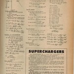
Building Your Own Sports Car: Part 2 – Road & Track, October 1951
An Analysis of the problems involved
By Charles G. Manning
Frame:
It is obvious that it will accomplish little to supply adequate damping for a suspension that is tied to a frame so flexible as to bend and twist like an undamped spring. The absolute requirements of frame rigidity are, of course, dependent on the layout of the particular car under consideration.
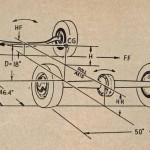
The author proposes that for a competition automobile, the frame torsional rigidity should like between 5000 and 15000in-lbs,/deg. twist. Determining this frame stiffness is best illustrated by an example. Suppose we have a frame 45″ wide and 100″ long between front and rear axles. We support the frame on blocks at two opposite corners and begin loading the free corners. When the front of the frame has twisted 1deg with respect to the rear of the frame, we note the load on the free corners.
The load on the free corner (to twist the frame 1deg) multiplied by the frame width at that corner, measures pounds/degree. In our example, if 200 pounds were necessary on each free corner to twist the frame 1deg–the torsional rigidity is 200 x 45 = 9000 in-lbs./deg. twist.
A frame with adequate torsional rigidity automatically has sufficient bending rigidity and has several times the strength necessary. Therefore, aluminum or high strength steel offer no advantages either from a weight or a rigidity standpoint, over low strength steel.
There are four basic types of frames:
- single tube “back-bone” type” (Skoda)
- large-diameter tubular rectangle (BMW)
- tubular tress rectangle (XK-120C)
- conventional box section rectangle (American cars)
Of the four types:
- type 3 can be made the lightest (for a given rigidity) but is also the most difficult to design and build
- type 2 is by far the simplest to design and build and will be nearly as light as type 3
- types 1 and 4 will always weigh several times as much as either type 2 or type 3
Brakes:
In a road race, one must slow down just as often as he speeds up; the hottest car in captivity cannot expect to finish near the front if slowing down for a corner results in “fade” to the point of uselessness.
Brake fade is caused by a change in coefficient of friction between the brake linings and drums. Leading shoe brakes depend on the friction between the linings and the drum for their self -energizing feature. As the brakes heat up, the coefficient of friction drops off.
Hence, the particularly bad fade characteristics of two leading shoe brakes. Some European competition car have two or even three trailing shoe brake and appropriately larger hydraulic cylinders in the drums. This approach does help counteract brake fade . . . however, charred linings may result.
In combating brake fade, venting thru the backing plates helps some as do very large brakes with air directed over the drums. Brake fall in two general classes:
- The heat absorbing type (aircraft, disc or etc.)
- The heat dissipating type (vented, finned or artificially cooled brakes)
Let’s first discard the heat absorbing type as they are designed to occupy a small space and to be used only very intermittently.
The heat dissipating type are suitable for more frequent use and they rapidly dissipate heat. Probably the most significant developments along this line is the Alfin brake drum. The process is a Fairchild Aircraft patent in which an aluminum muff is bonded to the outside of the cast iron brake drum and fins are then machined in the aluminum.
The large surface area of the fins and the excellent heat transfer coefficient of the alloy combine to form a remarkably efficient brakes drum. It should be emphasized that cast iron fins are useless . . . the heat transfer is too slow.
The iron fins may be cool enough to touch while the inner surface is actually read hot! The same applies to “pressed on” aluminum fins, which have a large temperature drop from the cast iron to the aluminum. The hear will not flow thru the junction unless it is chemically bonded.
Steering:
We’ve read glowing accounts of steering gears so completely friction free that the steering wheel will whip with the car parked in a slight breeze! If your car weighs 4000 pounds with 70% of the weight on the front wheels, then you had better look one of these outfits up and take along your check book and some co-signers (or get a Chrysler power-boost.)
If, however your car is to weigh 1000-2000 pounds with less than 50% of the weight on the front wheels, don’t worry about a little extra friction. Instead, let us choose steering that can be adjusted to almost no backlash (or play) and can be purchased for a reasonable price.
Almost any stock American car steering is adaptable and the difference between them is small. Drag link steering reduces wheel lock (larger turning radius); while cross steering may interfere with radiator location. There is little choice between the two.
All stock steering gears have one thing in common . . . . they are too slow–between 20 and 28 to one: or 4-5 turns, lock to lock. In the light, short wheelbase, sports car, front wheel motion required to control a power slide must occur so fast that there is not sufficient time to spin the steering wheel back and forth. For our design, about an eleven to one steering ratio will be desirable, giving approximately 2 turns lock to lock.
Probably the easiest method of lowering the steering ratio is to lengthen the pitman arm. Long pitman arms are available for some steering systems but building a new one is relatively simple. If the spline on the one end or the taper on the other cannot be duplicated, they can be cut out of the old pitman are and welded into a new blank, flame-cut from 1/2 inch steel plate.
The new plate should completely encircle the old ends so that the welds need work only in shear. Magnafluxing all steering gear parts is recommended.
Engine Cooling:
The choice of radiator can make or break the whole design. However, if a fan is used, cooling ceases to be a problem: provided that fan blades can be made to stay on their hub at high rpm. Some experimenting with fan diameter, number of blades, their pitch, and ducting may also be necessary.
On the other hand, a fan soaks up 5-10 hp (and sounds like it’s using 100). The other alternative is a big enough radiator so that a forced draft isn’t required. If a fan is used, we need only concern ourselves with total heat exchange area.
For example, a radiator one square foot in frontal area and about 3 inches thick will do the job if enough fan hp is used to pull the air thru. With no fan, the radiator must have a very thin core (1 1/2″) or the air will flow thru too slowly to do any appreciable amount of cooling. We are, therefore, stuck with a large frontal area radiator, a large grille opening and plenty of exit area. In addition, the radiator water will gradually come to a boil if the engine is allowed to idle while the car is standing still.
One solution is a de-clutchable fan that can be engaged or disengaged from the driver’s seat while the engine is running. Then in thick traffic, on a long steep hill, or with a tailwind we have extra cooling available . An excellent fan is the eddy current drive type available for ‘416-’48 Fords. The battery furnishes power to operate an electric clutch and the fan is controlled by a switch.
A large variety of mechanical friction drive designs is also possible. A swinging arm may be fashioned to hold the fan which is moved to engage its pulley with the water pump pulley. Don’t consider electric fan drive because a fan driven by a 5hp, 6 volt continuous duty motor, supplied by a 700 amp generator, would weight about 250 pounds and would cost a small fortune.
Determining the absolute size of radiator depends upon too many factors for the builder or designer. However a high performance sports car will need at least double the ratio of radiator cooling area to gross weight found in passenger cars. Approximate radiator cooling are would be the frontal area of the core times the core thickness, keeping in mind that our core thickness must not exceed 1 1/2-2″ if no fan is used.
Engine:
In an attempt to say something useful about engines in less than 100,000 words, we’ll confine this discussion to desirable and undesirable engine characteristics as related to sports car design.
First, we want a fat hp/rpm curve. By that we mean not only a high maximum output, but the ability to hold something near maximum over a wide range of rpm. In short, we are interested in the area under the hp/rpm curve over the range of rpm we expect to use.
This useful range is determined by the number of forward speeds available in the transmission and the type of race course. Thus, the engine with the lower peak hp will show a faster lap time with a transmission such that the useful rang is 3000-7000 rpm.
A second important characteristic is the ability of the engine to hold maximum output for a long interval of time. Engines with iron heads and pistons or improperly cooled exhaust valves are often bad from this standpoint. After a minute or two of running at full throttle these engines develop hot spots which raise the octane requirement of the engine. Large power loss due to detonation or part throttle running is then inevitable.
Engines fitted too tightly also have the same characteristics. But for a different reason. These experience an increase in friction hp with increase in BMEP, and the extra friction usually come from insufficient piston clearance. In practice, engine accessories are often the cause of similar power losses. All too often, new spark plugs which are incapable of firing against 140 psi pressure will be installed in an engine that will crank 150psi cylinder pressure on the starter.
If your engine is 8 1/2 or 9 to one compression ratio, this is your problem, as very few commercially obtainable plugs will fire at 150 psi and fewer still when the plug is hot. We should also consider parts availability when choosing an engine. Any engine used for active competition will have a high rate of parts consumption.
If you order a new set of bearings or valves and they take six weeks to arrive, (and 12 weeks to return and exchange for the right ones) the maintenance becomes a real problem. We should also resist the dirt cheap D.O. 2 stage whose manufacturer disappeared from the face of the earth ten years ago.
A set of hand forged and machined connecting rods can come to a ridiculous price. This is in contrast to the ads for production engine overhauls which state, “New pistons, pins, and rings . . . . pins fit and rods aligned . . . . only $18.00.”
Summary:
This article has more to do with understanding the mindset of those who built our favorite fiberglass sports cars in the ‘50s than you might imagine. Looking back ’60 years, we tend to view these cars as “from the era” and in some cases “quaint.”
The guys who built the cars back then – like Chuck Manning – were trying to build cars that would outperform the best of them at the time. And each of you who have one of these cars, would benefit from reviewing Chuck Manning’s thoughts and advice in this 2-part article. It covers all the bases and focuses on the very core of a successful and well-designed sports car “build” from the ‘50s.
I also appreciated hearing Manning’s first-person thoughts on the use – or non use – of a fan. So many of the specials we have or are restoring do not have fans. For awhile, I thought there was a mystical parts procurer – traveling the country just ahead of me and removing mechanical fans from every “Special” we found. Chuck Manning eloquently addresses the fan/no fan issue in “Part 2” of the story.
That completes the second part of the story on how Chuck Manning built his race car, and these two stories printed in Road & Track became the basis for many young men to enter the racing scene back in the day – with a winning combination of speed and on a budget.
Thanks again for Joel’s willingness to help place this article here on Forgotten Fiberglass for everyone’s review, and be sure to check on Joel’s website and watch the progress on Joel building his own “Manning Special.”
Click here to visit Joel’s website on building his own “Manning Special”
But that’s just the start of what Joel has found in his quest to learn more about Chuck Manning and his expertly designed and built sports car. Wait ‘till you see what Joel has to share in the future…..here at Forgotten Fiberglass 🙂
Joel and I hope you enjoyed the story, and until next time…
Glass on gang…
Geoff
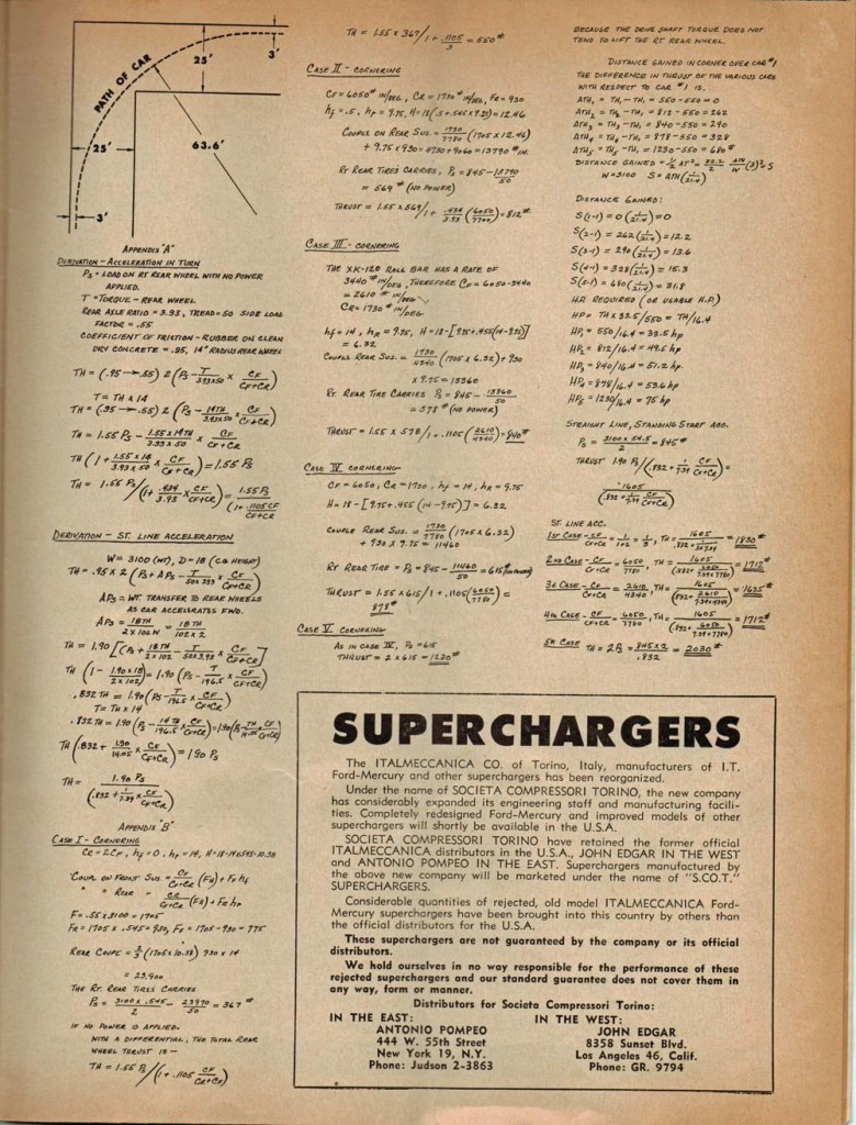
——————————————————————-
Click on the Images Below to View Larger Pictures
——————————————————————-
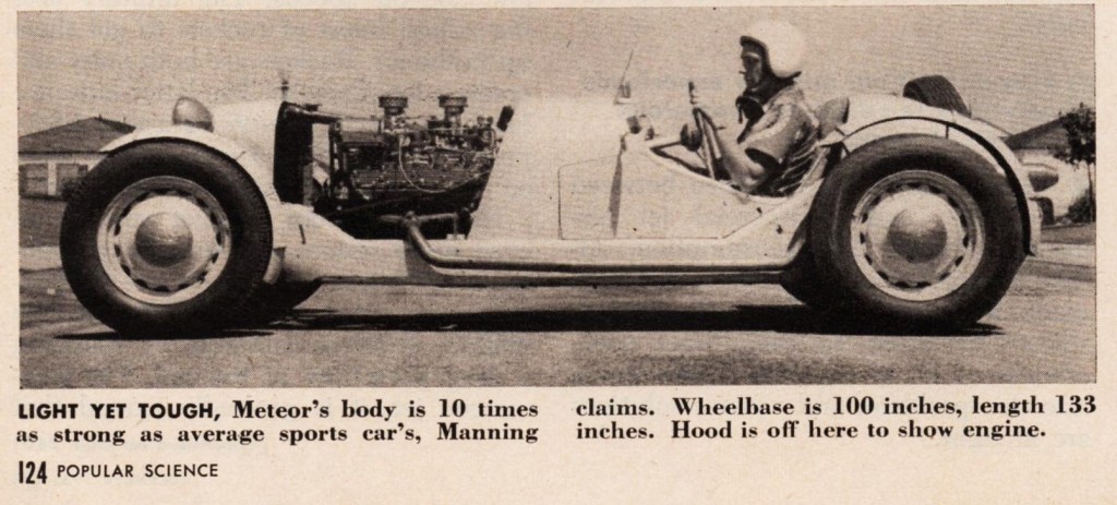
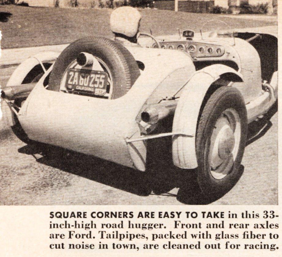
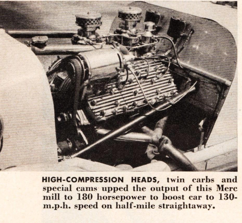
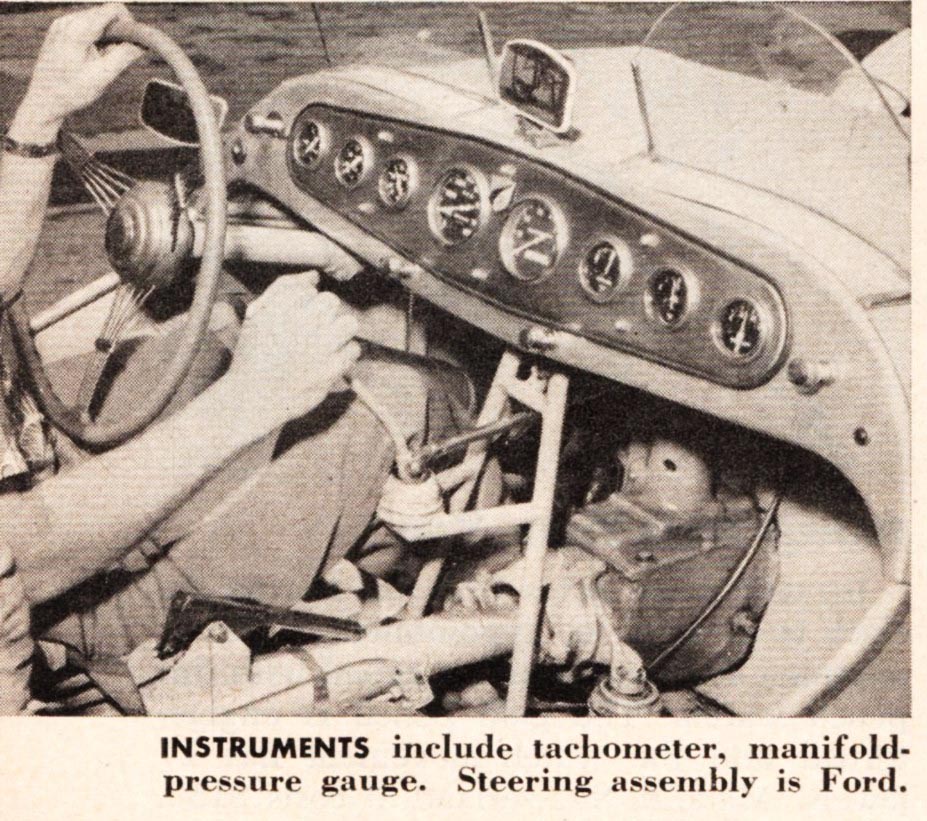
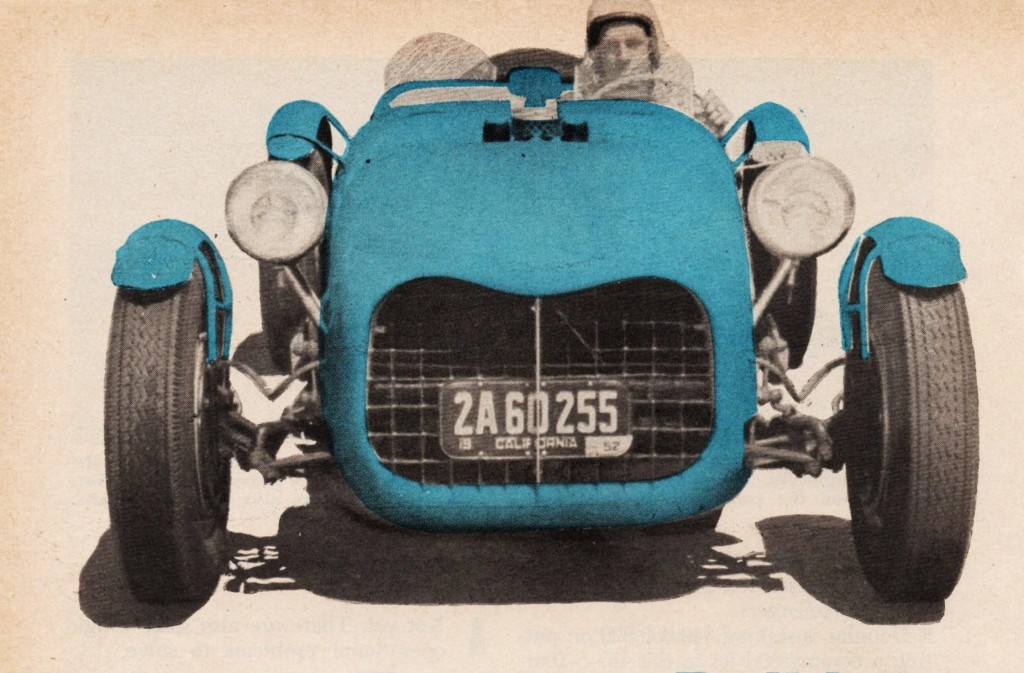
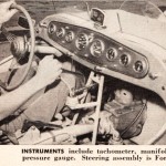
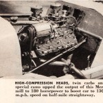
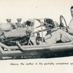
- Picture And Caption From December ’52 Issue of Popular Science
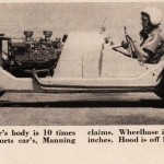
- Picture And Caption From December ’52 Issue of Popular Science
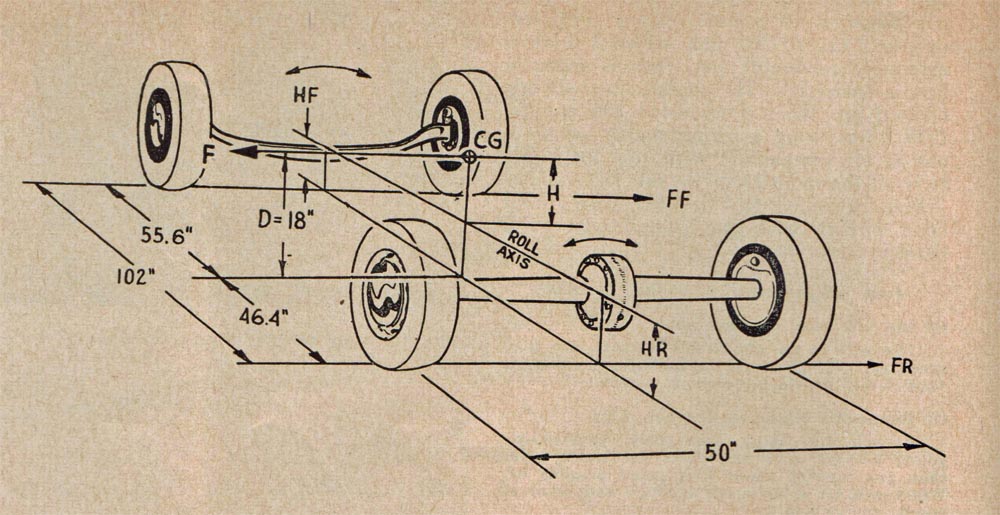




~ It’s remarkable how far ahead of manufacturers Chuck Manning’s intuition and experience were in 1951. I didn’t read anything which has been contradicted in the intervening years. thanks, Joel & Geoff. sc