Hi Gang…
Small books were published throughout the 1950s by various automotive magazine publishers. The largest producer of these books was Petersen Publishing – the organization that brought us Motor Trend, Hot Rod, and other such luminary magazines. But Fawcett Books was not far behind. In fact, it was actually one-year ahead.
Trend Books came out with their first book called “Custom Cars” in 1951, but it was Fawcett Books that came out with a book on cars called “Sports Cars and Hot Rods” one year earlier in 1950. It was a race to produce these small booklets on various sports car, hot rod, and automotive topics, and these two companies would battle throughout the 50s to produce a wider and greater variety of booklets – booklets which we now treasure as a window into the times of building, driving, racing, and modifying your car in the ‘50s.
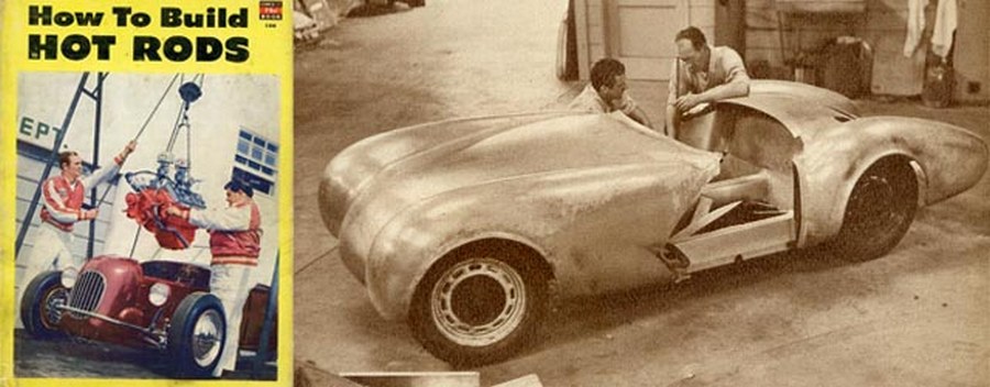
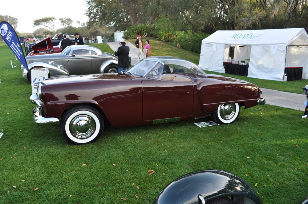
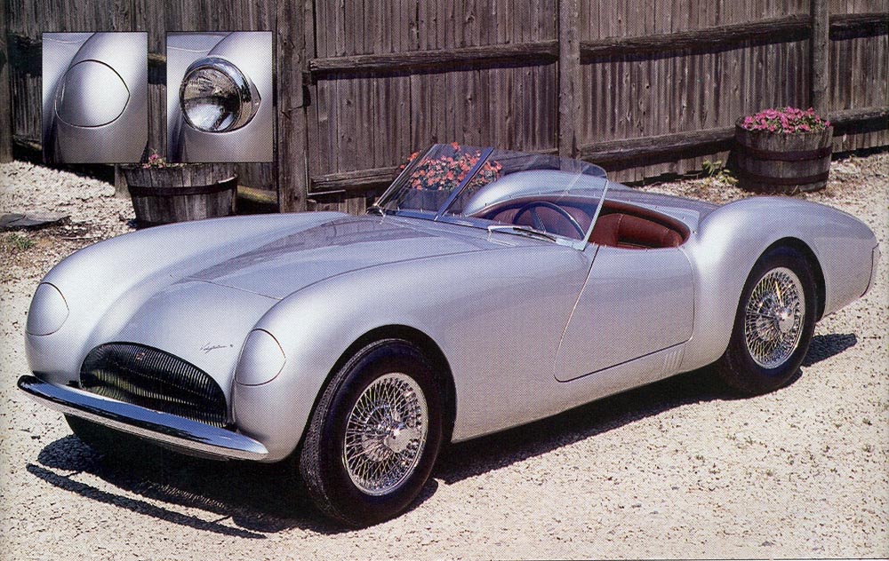
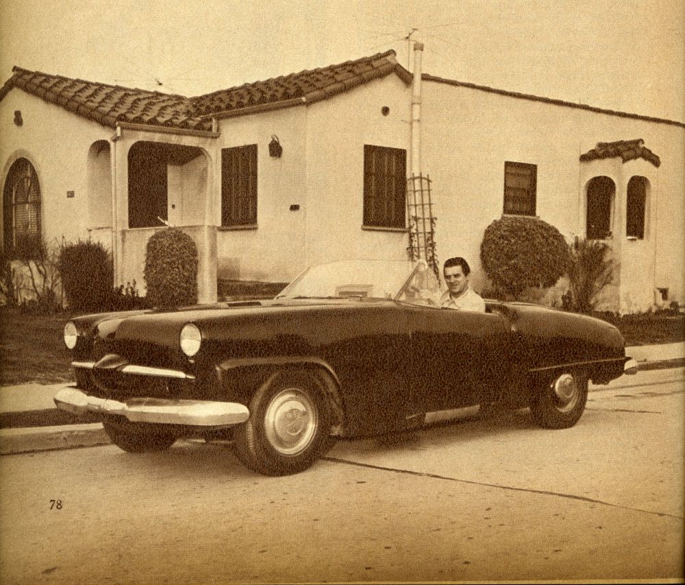
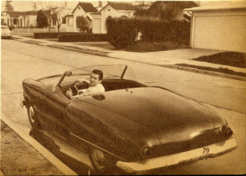
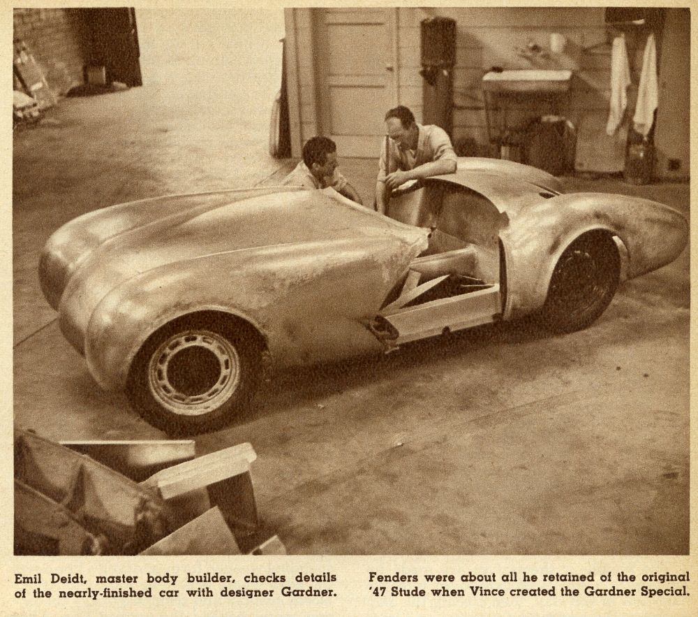
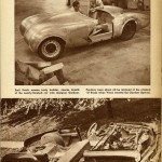
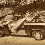
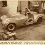
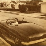
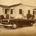
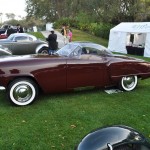
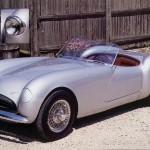
Take today’s article. This article was from a series of interviews with Vince Gardner – one of the earliest designers of coachbuilt, handcrafted cars in the postwar era. In the late 1940s, he designed and built a custom car modified from a Studebaker body and chassis known as the Gardner Studebaker. Just a few short years later, he designed and built from scratch – with the help of Emil Deidt – a handcrafted sports car called the Gardner Vega. Both can be seen below.
Today’s story is from Fawcett’s 1952 book on “How To Build Hot Rods” and features an extraordinary number of articles focused on building and designing your own hot rod – from scratch. Nestled in among all these articles is an amazing find – a 10 page (yes….10 page!) article from Vince Gardner showing how he built his Gardner Studebaker in the 1940s and shows his work in progress – the Gardner Vega.
Throughout these 10 pages we see photo after photo and word after word on how these cars were built and – most importantly – how someone could design and build their own car with careful study of the skills necessary to do so. Most interestingly, after he spends 9 pages discussing and showing how to design and build a car out of steel or aluminum. Then, almost on the last page he then begins with the following words:
“The best alternative, in my opinion, is to make the body of fiberglass, that super-durable plastic that can be molded in one piece.”
And for the next six paragraphs until the final word in the story, Vince Gardner discusses the advantages of doing in fiberglass – what he has labored years in doing in steel. This article was published in 1952. Since fiberglass sports cars were introduced in late 1951, no doubt what we are seeing here is the awareness of one designer and fabricator – going through what many people were thinking at the time, and that was the benefit of using fiberglass to design and build your own handcrafted car.
In this one article, we see the awareness shift to building one-off custom cars, sports cars, and concept cars out of fiberglass – the lightweight, strong “carbon-fiber” of its day. The new “wonder-material.” And for all of the reasons above and more, this article is worth the time to review in word and photo.
Go get ‘em gang!
Create Your Own Custom Body
How To Build Hot Rods
Fawcett Book #156, 1952
By Vincent E. Gardner as told to Louis Hochman
Vincent E. Gardner began his career as an automobile designer back in1936, working as a model builder on the Cord. From there, he moved on to Briggs Manufacturing as a draftsman, then to Budd Manufacturing, where he started as a model builder and worked his way up to chief designer in the space of one year. In 1943, he joined Studebaker as a designer.
The latter part of 1951, Vince left his job at Studebaker and went to California to design and build his own sports cars. His plan is to someday manufacture a Fiberglas car body which will sell in kit form for about $1,000. The body will be composed of interchangeable sections to provide customers with a variety of design possibilities, simply by ordering different combinations of body parts. With this plan, he hopes to bring to the auto enthusiast a low-priced car body that can be fitted to any conventional chassis.
Vince Gardner is unique in that you have to go far to find a man of his background with the pioneering spirit to forsake the steady salary of a plush Detroit job and devote his time to designing and building cars on his own.–Ed.
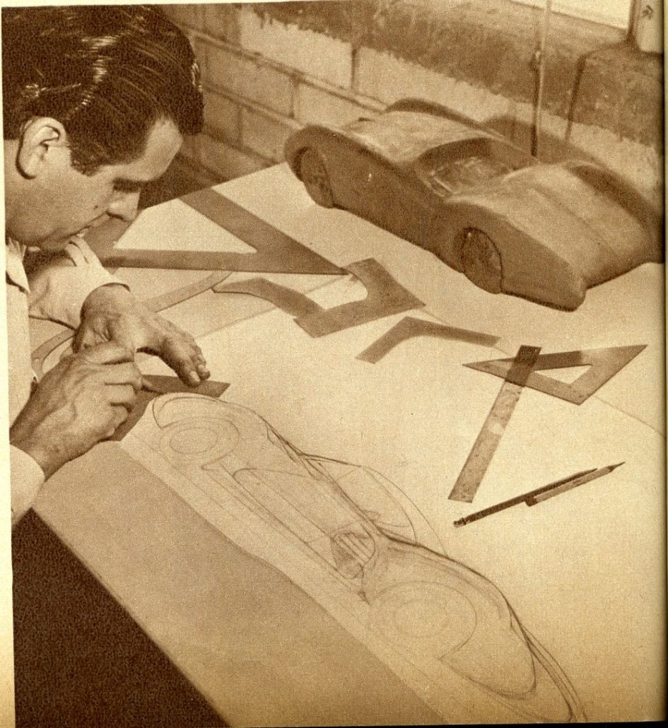
If you’re anything like the average car owner, you no doubt dream of some day owning a flashy car that is the only one of its kind–a car that you yourself designed and built. Maybe you’ve kept this dream in the background because you feel that you’re not qualified to design your own car, much less to build it yourself. Such reasoning is pure pessimism, for if you have an ounce of imagination and originality, you can design your own car body, and you can do it with the same materials that the big Detroit companies use, namely, pencil, paper and clay.
Designing a car body doesn’t mean going overboard in the field of fantasy and creating a Buck Rogers spectacle designed to confuse the befuddled public as to the true purpose in life, unless that’s the direction in which your tastes jet. You’ll have just as much fun, and a good deal more success if you stick closer to the more conventional by-paths of natty car designs. Here’s the formula.
To begin with, a design usually starts with an idea. Shapes take form in your mind long before you put them down on paper. These shapes are usually inspired by a variety of influences. They might be a combination of existing shapes–the fenders of one car, the hood and cowl of another, the rear end of a third, and so on. Or some existing design that appeals to you might have inspired a similar, modified version.
If you find ideas hard to come by, study the designs of existing cars and figure out ways of changing certain features to suit your own individual tastes. There’s no law that says you can’t improve on the other fellow’s baby, and you’ll be surprised to see how original your design will look.
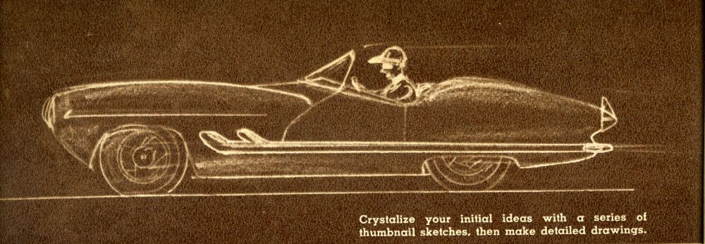
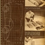
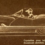
As soon as your ideas begin to formulate, they should be sketched in either perspective drawings, or a series of flat and end views. Small thumbnail sketches will do–just enough to give you a visual record of the idea. The flat side view is usually enough to capture an idea. Having decided on the general appearance of your car, the next step is to decide on the wheelbase and find a chassis to correspond–or choose a chassis and alter the wheelbase to suit.
To be attractive, a sporty car should be low-slung. Therefore, another modification will be necessary. The engine will have to be lowered and set back if the hood height at the cowl is to be less than 40 inches.
Rather than lower the engine, however, it would be advisable to alter the springs, both front and rear, and thereby lower the entire chassis three or four inches. This latter change will give you a more satisfactory seating position by bringing the floor nearer to the ground.
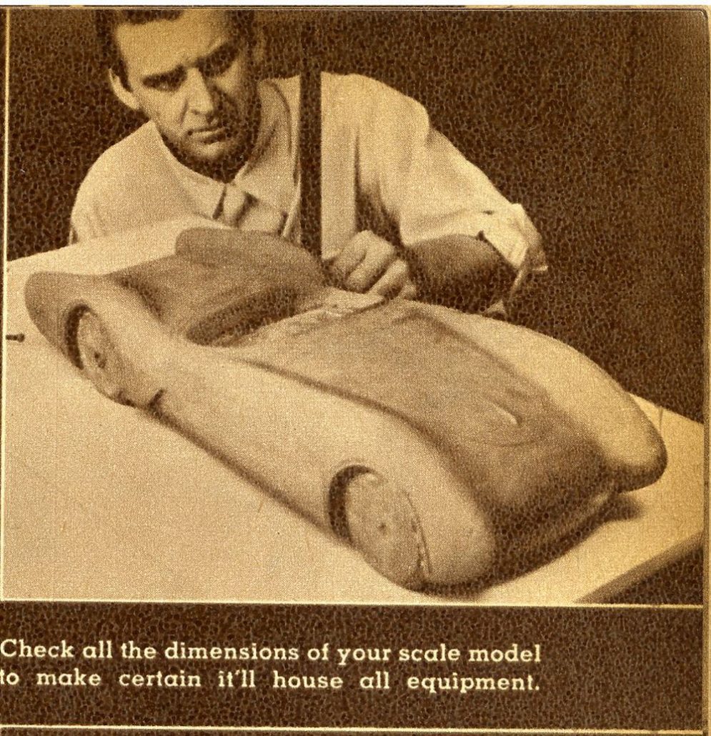
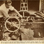
Now comes the job of making an accurate three-view drawing showing the correct wheelbase, engine location, radiator location, windshield, steering wheel and ground clearance–and don’t forget the seating position! Also remember the top, and be sure to provide plenty of headroom. Most important considerations in a car of this type are comfortable seating, head room, clutch and brake pedal location, accelerator pedal location, windshield location, and visibility. If you have a good comfortable seat and your visibility is right, you have a comfortable car to ride in.
Another thing you don’t want to overlook is cooling. You can’t get away with just a little hole in front and expect the air to cool a great big radiator.
There’s some sort of formula for figuring the size hole required but I’ve yet to see such a formula work out every time in practice. When I used to work in the designing department at Studebaker, the engineers would figure that they needed so many square inches of frontal area to cool a given radiator–so we’d give it to them. They’d build a car accordingly, take it out on the proving grounds, run it up and down the hills, give it the old torture treatment, and bring it back boiling–not enough cooling? So they’d cut the hole bigger.
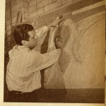
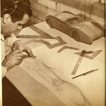
The accurate three-view drawing should be made to either 1/8- or 1/4-in. scale on paper that is ruled off in squares, each line representing a distance of 10 in. For a 1/8-in. scale, the graph lines should be 1 1/4 in. apart, while for a 1/4-in. scale, space your lines 2 1/2 in. apart.
Your scale drawing starts with a vertical line, marked “zero,” running straight down through the center of the front wheel. Then, all subsequent vertical lines going from that point toward the rear of the car, are successively marked, 10, 20, 30, and so forth. The vertical lines running from zero toward the front of the car are marked successively minus-10, minus-20, minus-30, and so on. It’s a simple method and commonly used in the automobile business. While accurately sketching in your design this way, you can allow for the required clearances.
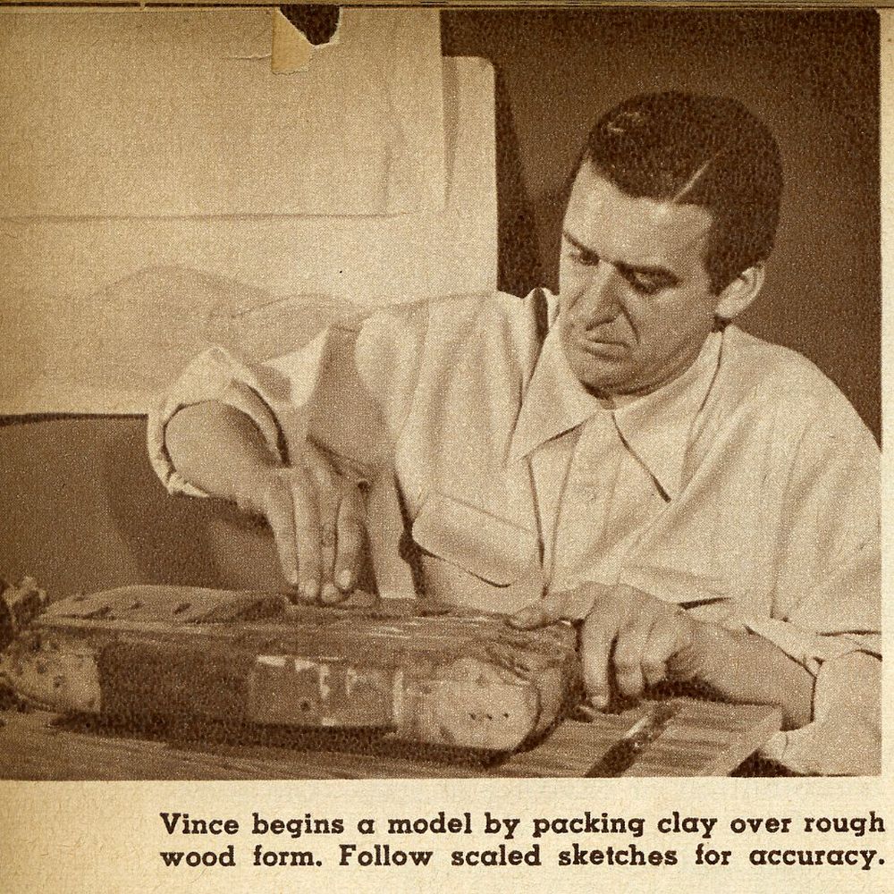
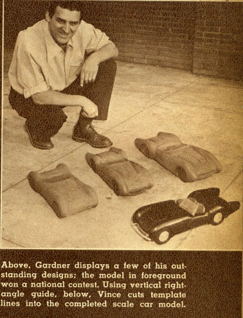
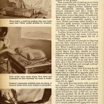
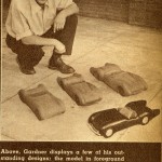
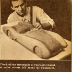
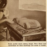
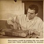
Now comes the $64 question! Having made an accurate set of scale drawings, how do you go about translating these two-dimensional sketches into three-dimensional forms? The answer is to build a tiny model to the same scale as you made the drawings–not of balsa wood, or plywood, but of modeling clay. Modeling clay, available at any art supply store, provides the ideal means of molding and forming the various shapes into an accurate scale model.
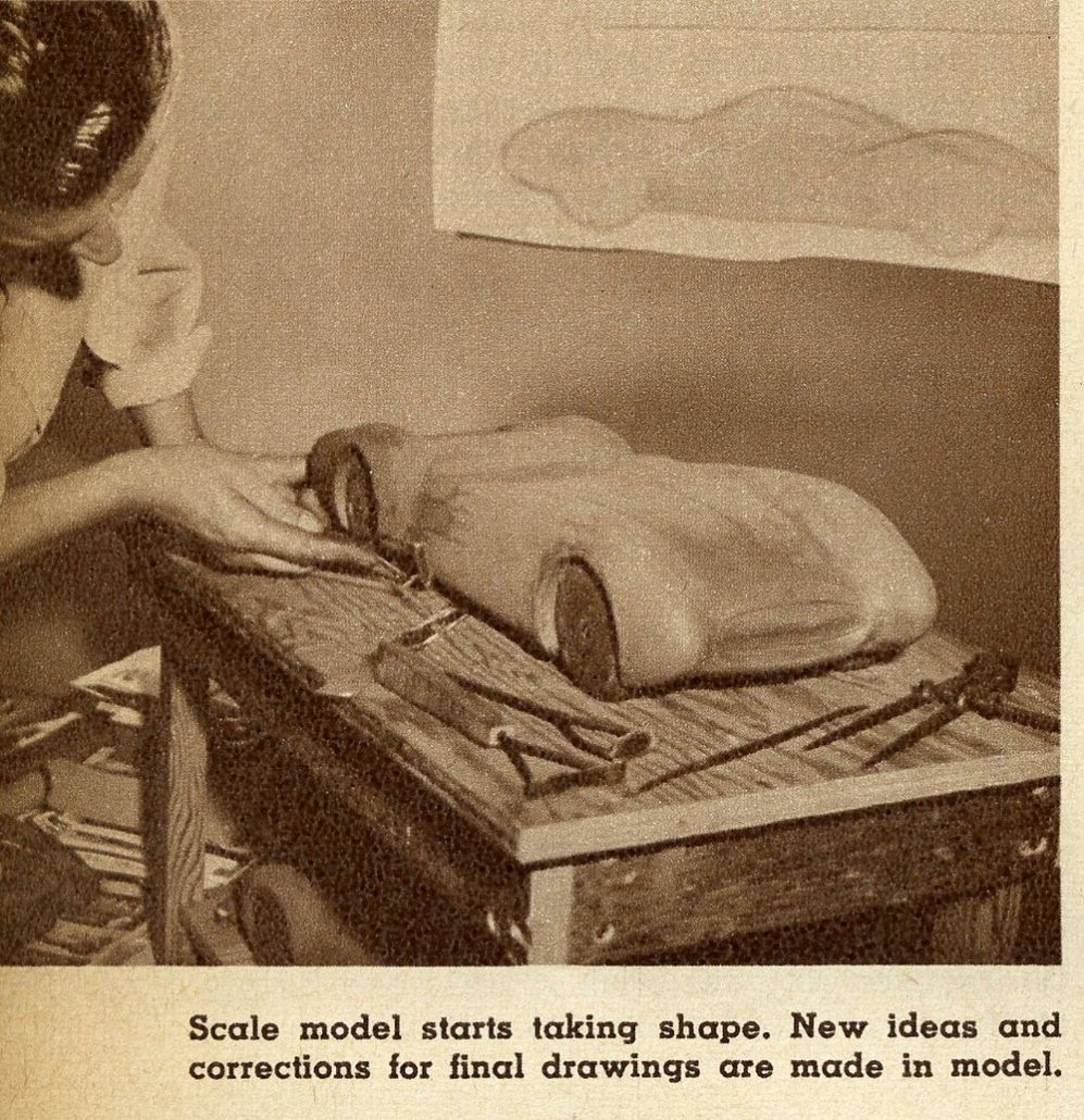
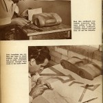
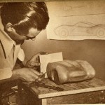
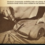
Start your clay model by packing the clay onto a rough-cut wooden block to which a set of plywood wheels of the correct scale representing the wheelbase have been nailed. A simple set of modeling tools for working the clay can be made by welding short 1- to 2-in. lengths of hacksaw blade to forked metal rod handles as shown in the accompanying photos. The stops of these blades can be sharpened to knife edges for smoothing the clay. The sawtoothed edges are used for rough shaping.
As you work the clay up to the final shape of your car, you will find yourself making many changes in the design, due to your new perspective in seeing your idea take three-dimensional form. Finally, your clay model is finished and you’ve decided that this is it! Isn’t it a beauty! Because you’ve made some inevitable changes in the clay model, it will be necessary to correct your original scale drawings.
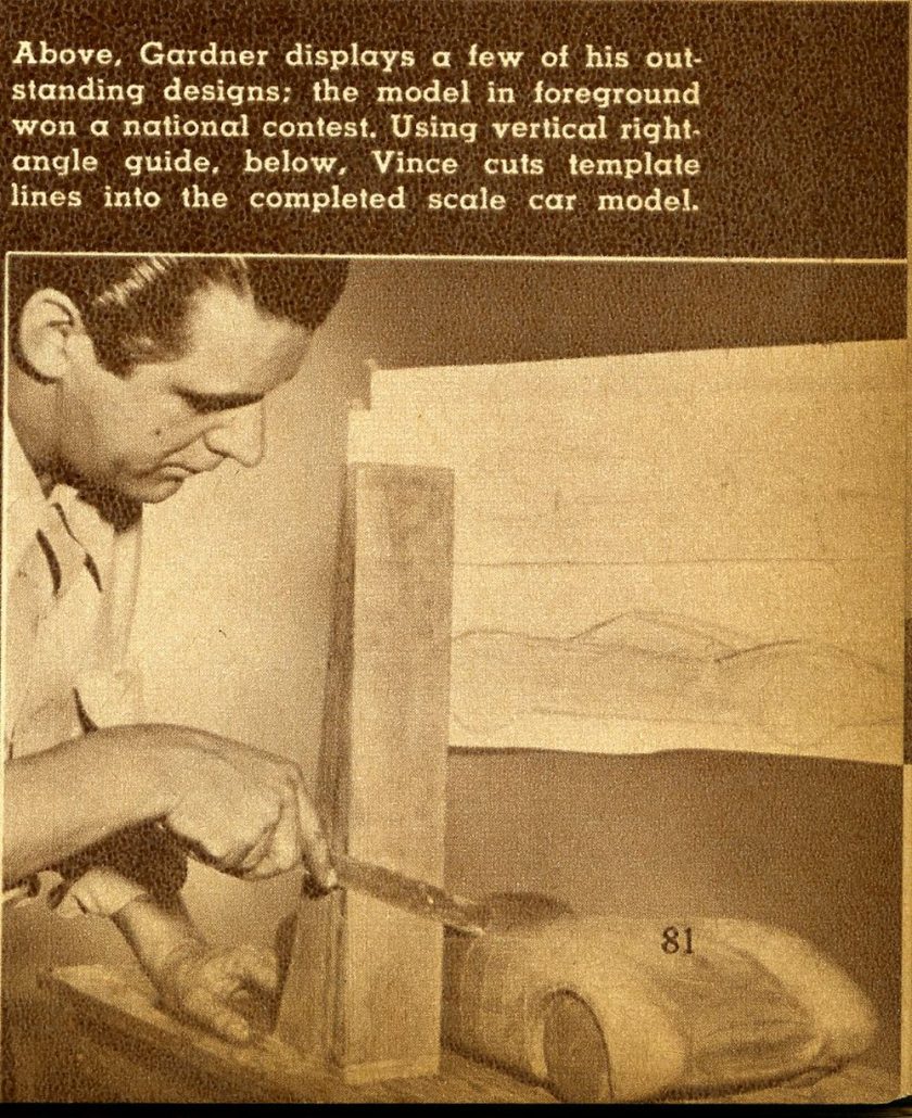
This you do by cutting sections in the clay model about 10 in. apart and making cardboard templates of the shapes at these points. The templates are then laid over the corresponding portions of the original scale drawings and the drawings are altered to match them wherever they vary.
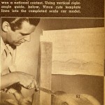
A simple way to make these templates is to cut vertical lines down through the clay model exactly as the lines that run down through the scale drawings. The spaces between these lines will represent distances of 10 in. on the full-scale car. A handy guide for cutting these lines accurately consists of a length of heavy wood 3 in. wide, which is nailed to a base strip of plywood to form a perfect right angle. With the plywood base held firmly down to the work table along side the clay model, a steel rule can be pressed against the flat surface of the vertical portion of the right angel guide and slid down along it to cut straight accurate lines into the clay model.
Since both sides of the car will be the same, the templates will have to be made of only one side of the car–either the right or the left side. Therefore, the clay model can be bisected with a line running longitudinally along the middle of the top and this line can be used as a guide in making the templates.
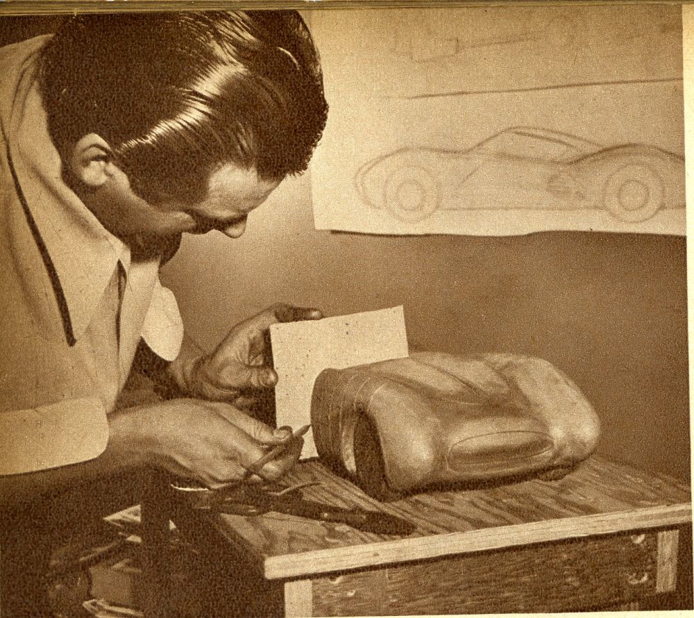
The templates themselves are made by sinking thin sheets of cardboard into the lines cut in the clay then tracing the clay forms on the protruding portions, and later cutting away the cardboard up to the traced outline. Each template should be identified by marking it with the number that corresponds to the line from which it was cut.
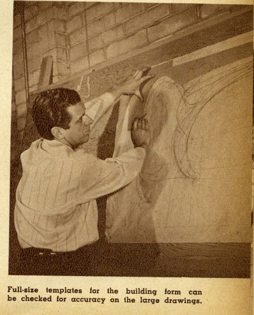
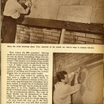
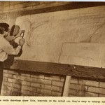
The next step is to enlarge these templates to full size by copying them onto a large sheet of paper that has been ruled off with 10-in. squares. A projector large enough to take the 1/8-in. scale drawing or the small templates would be ideal for making the full-size enlarged templates. However, in the absence of a suitable projector, the templates can be enlarged simply by copying them onto the larger paper, following as accurately as possible the patterns as laid out on the squared-off graph. This job will be easier if you take the large sheet of paper onto a large plywood panel.
After the templates have been copied over onto the larger scale, blacken the back of the large drawing with soft pencil and carbon-copy the enlarged templates onto sheets of heavy cardboard to make full-sized templates for the final stages of construction. If you want, you can use these full-scale templates to make a full-size working drawing of the car for a final check to see if everything is just as you want it. A full-size drawing will often reveal details and angles that escape you in the small scale drawings and model.
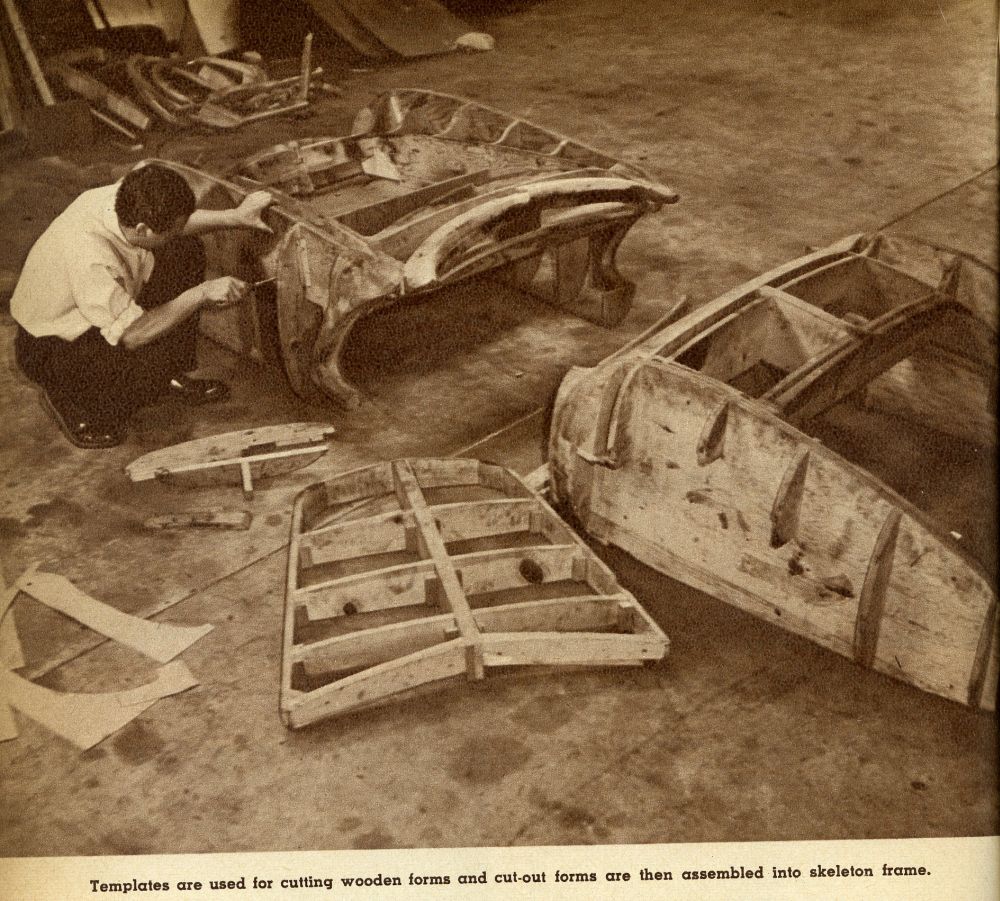
Once you are satisfied that you have what you want, trace the large templates off onto wood (1/2-in. plywood is ideal) and cut the forms out on a bandsaw. You don’t have to work too accurately in this sort of thing–just so you come fairly close. After all, it’s not a precision piece of machinery that you’re building, just a guide for the metal man so he won’t have to use his imagination.
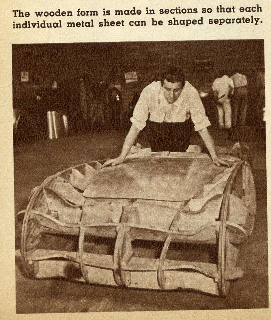
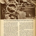
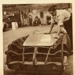
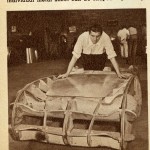
With your wooden forms cut out, the next step is to assemble them into a skeleton shape of the car. The cut-out wooden shapes are spaced 10 in. apart to correspond with the sections of the model from which the respective templates were made. Also, the entire wooden form is made in sections, each section representing a separate metal form. This is because you have to form the body in sections which are later welded together to make the single-piece body.
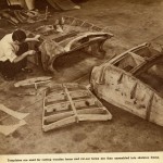
As the metal sheets are shaped to fit over these wooden forms, they are left a little full, about 2 to 3 in. extra at the edges, so that they can be trimmed to the exact size and welded together. This is done by laying the formed metal shape over its corresponding wooden form, scribing a line down the edge where it is to be joined to its adjacent section, and trimming away the excess metal beyond the scribed line. After the adjacent section has received the same treatment, the two sections are butted together and welded to form a single piece. Here, too, absolute accuracy is not a must. Variances of 1/8 to even 1/4 in. won’t matter if the final result still appeals to the eye.
How many individual sections each portion of the car body is composed of depends upon the particular design. The car, of course, is planned to fit the chassis–floor pan, hinge pillars, fire wall, gas tank, luggage compartment–all are planned according to where you intend to put everything.
Unless you can do all your own work and form the metal yourself, you’re going to find the building of a metal body pretty expensive. Labor comes high–about $4.00 an hour, including overhead–and a lot of man-hours go into the making of a car. The best alternative, in my opinion, is to make the body of Fiberglas, that super-durable plastic that can be molded in one piece. I don’t intend to go into the technique of handling the material here, but I can give you a few helpful, money-saving hints.
The process of designing a body in Fiberglas is the same as that described for a metal body; that is, making the scale drawings, then the clay scale model, and enlarging the small templates to full size. However, from this point on, you proceed a little differently in that, instead of building a wooden skeleton form, you actually build a full-scale clay model of the car, complete to the last detail, using a rough wood lath form underneath. This clay model is then used to make the master mold from which the finished Fiberglas bodies are made.
The greatest item of expense here is the cost of the clay for the full-size model, which could easily come to a few hundred dollars; about 500 pounds of clay will be needed. However, you can cut down considerably on this expense by sharing it with several other friends who also want to design and build their own car bodies.
First, you must all agree on the chassis and basic pattern of the car. Then, you get together and chip in for enough clay to build one full-size model. Say, one of the group has an idea and he builds his model first. He makes his molds and he’s finished.
Now, suppose the next member wants his car to have a fin on the rear fender–so he adds a fin to the clay model. If he wants a different nose, he changes that too, right on the original full-scale clay model. After he’s made all the changes he wants in the original design, he makes his molds and the clay model is then free for the third member to modify.
In this way, each member of the co-op team has a chance to design his own car body and use the same basic form to work on and pull his molds from. It isn’t necessary to build a completely new full-scale model each time. After all, once you’ve worked out the seating and visibility, you wouldn’t want to change that; all you’d want to change is a few shapes and forms of the external design. So with this system, you can go ahead and build dozens of car bodies, making each one different.
So there you have it! Use whatever method you like–but don’t say it can’t be done.
Summary:
There you have it – the story of a fabulous designer who could move from concept to design to fabrication to completion with the best of them in the world. And he wasn’t shy to use talent for metal fabrication such as the esteemed Emil Deidt – a coachbuilder of great postwar provenance.
There are so many reasons why this article is important for our research, and these include documenting the design and build process, showing and teaching others how it was done back in the day, and a realization – at ground zero – of when fiberglass was introduced as a viable product for building sports cars, custom cars, concept cars, and other cars. This new wonder material – fiberglass – was ready, willing, and able to be used. And our favorite designers and builders of the period took off in a flash with the same realization.
Perfect timing for a great read here at Forgotten Fiberglass!
And for those of you who wish to learn more about Vince Gardner, the man, and his career, be sure to check out the October 2007 issue of Collectible Automobile. There’s a great biography of Vince Gardner and his history.
Hope you enjoyed the story, and until next time…
Glass on gang…
Geoff
——————————————————————-
Click on the Images Below to View Larger Pictures
——————————————————————-



I had no idea that so much planning goes into make a custom sports car. It seems like it would be smart to get a professional to help with making the model. That way, you know that the angles will be right. After all, if the model isn’t accurate it could change what the final look of the car is.
Pingback: Custom Car Design Software – Marcel Lawyer
Pingback: Designing Your Own Car – Marcel Lawyer
Interesting. I have a project for an atv to put a small body on. To look like a future car
I am interested in producing with a aluminum body the DB5 Aston Martin 1965 same car as James Bond in Movies Thunderball and Goldfinger can it be done
Hello Rob and Tom,
Thank you both for replying to my post. I look forward to finding the episode of ‘American Pickers’ that you mentioned.
Meanwhile, in answer to your question…yes! I did know Mr. Gardner. I would love to talk with you so we’ll have to figure out how to do that. (I’ve some ideas) It will take some digging, but I’m pretty sure that I can find some photos of your uncle that you don’t have. (Studebaker 1940’s and early 1970’s) I’d love to share them with you.
Hello Lucy,
Rob and I would be very interested to hear about your memories of and connection with our uncle. You can contact me at tjk4856@charter.net
Thanks!
Vince Gardner created a ridiculously comfortable, fiberglass, ‘TV’ viewing floor chair in the early 1970’s. The one I had was orange, ‘the’ color of the time. I have not seen one since. It was probably a prototype.
Vince Gardner was my uncle and I grew up in Duluth, MN. We have three of the chairs he designed. One rocker and two on pedestals. One of the chairs was found on a recent episode of American Pickers. Did you know him? Thanks.
Vince Gardner was my Mother’s half Brother. It’s great to have the internet now and learn what Uncle Vince accomplished. I only heard bits and pieces while growing up, but did witness first hand his foray into fiberglass chair design and construction. I am a proud possessor of a chocolate brown pedestal model. Fans of “American Pickers” witnessed the discovery of a lime green pedestal model on a December 2013 episode from the Auburn, Cord & Duesenberg relocated factory in Oklahoma.
This is a profoundly important article. Ground zero indeed for early fiberglass. Imagine the impact that CAD software must have had on the designers and engineers of the time when they could then do much of this work with a keyboard, monitor and mouse. We sometimes forget how “revolutionary ” the digital revolution really is!
My younger friends assure me the “artistry” of the best of the digital designers is not lost just because they are using a mouse, digital pen or touchpad rather than a pencil or paint brush. Very comforting 😉
Great article,great pictures,great tips..of which I used quite a few of myself..I did my full size drawing on the living room floor..I went from thumbnail to full size,maybe I should have made a model first oh well..
Mel
This was a good read. Coolness!